Tuning #
For Road Runner to work best, it needs to be tuned to your robot. This process involves running several op modes and adjusting a set of parameters that capture the behavior of the bot. The entire affair shouldn’t take more than a few hours, and it can go much faster once you know the ropes.
Read this page very carefully, especially if it’s your first time. Most details are only mentioned once and you don’t want to miss them. Failing to fully complete one step in the sequence will often affect the next step, and you may be forced to start over when you don’t get satisfactory results at the end.
There are also some steps that only apply to mecanum drives or vary depending on whether you’re using drive encoders or dead wheels for localization. Pay attention to these directives and only complete the steps you need.
Once you’ve finished tuning properly, your robot should be able to execute pretty much any path you can specify. The shape of the path and the battery voltage shouldn’t significantly affect following. But the tuning can easily become out of date if weight is added or removed from the robot, encoders/motors are changed, or other major modifications are made. You may find yourself retuning the robot several times during the season, and it may help to practice the motions well before competition.
Make sure you have downloaded a quickstart project and opened it in Android Studio. Basic familiarity with FTC programming in Android Studio will help immensely. Consider reading through Learn Java for FTC and writing some of your own op modes before continuing.
Getting Help #
Try asking the community over on the FTC Discord. Many people over there have gone through the tuning process and can give the most practical advice for you and your team.
Make sure you’re running the latest version
of the library. You can check and update the library version in the TeamCode/build.gradle file
on the line that looks like implementation "com.acmerobotics.roadrunner:ftc:LIBRARY_VERSION_HERE".
If all else fails, open an issue here with as much information as you can supply:
- Tuning files (click the “Download” button on any tuning page)
- Link to robot code (GitHub repository or something)
- Version of the library you’re using.
- Robot logs (download from
http://192.168.43.1:8080/logs)
Drive Classes #
Goal: get basic hardware configured
Open either MecanumDrive or TankDrive depending on your bot.
MecanumDrive: The class assumes your four wheel motors are named"leftFront","leftBack","rightBack", and"rightFront"and your IMU is named"imu".TankDrive: The class stores the left and right motors inleftMotorsandrightMotors, respectively. To start, the class puts motors named"left"and"right"in the appropriate lists. If you have more motors, add them to theArrays.asList(...)expression.
Set the logo and USB direction of your IMU using the instructions on this page.
Feel free to change the default hardware names to match you robot configuration. For more information, check out the FTC docs.
In TuningOpModes, set the DRIVE_CLASS variable to the drive class you’re
using.
Then specify how the robot should track its position. There are a few built-in localizers:
- Drive encoders: This is the default. The IMU will also be used on mecanum to get better heading.
- Two (dead) wheel: Change the right-hand-side of
localizer =(mecanum, tank) tonew TwoDeadWheelLocalizer(hardwareMap, lazyImu.get(), PARAMS.inPerTick, pose). The code expects the parallel, forward-pointing encoder to be named"par"and the perpendicular one to be named"perp". - Three (dead) wheel: Change the right-hand-side of
localizer =(mecanum, tank) tonew ThreeDeadWheelLocalizer(hardwareMap, PARAMS.inPerTick, pose). The code expects the two parallel encoders to be named"par0"and"par1"and the perpendicular one to be named"perp". - Pinpoint Odometry Computer: Change the right-hand-side of
localizer =(mecanum, tank) tonew PinpointLocalizer(hardwareMap, PARAMS.inPerTick, pose). The code expects a Pinpoint device to be configured with name"pinpoint". Tuning for a Pinpoint device is the same as tuning for two dead wheels. - SparkFun Optical Odometry Tracking Sensor (OTOS): Change the right-hand-side
of
localizer =(mecanum, tank) tonew OTOSLocalizer(hardwareMap, pose). The code expects the OTOS device to be configured with name"sensor_otos". You can also set yourinPerTickparameter in your drive class to1.0, as the OTOS itself reports values in inches. The OTOS localizer also has four extra tuning OpModes described at the end of this guide, which should be done before tuning the rest of the robot. After those are done, the OTOS localizer can be tuned like the two dead wheel localizer, but without the odometry wheel locations fromAngularRampLogger.
If you choose to use dead wheels, drive encoders are not needed, and those encoder ports can be used for dead wheel encoders. You can change the names in
TwoDeadWheelLocalizer/ThreeDeadWheelLocalizerto reflect the motor names of the slots the encoders were connected to.Note that, for technical reasons, ports 0 and 3 on REV hubs are more accurate at high speeds and should be used for the parallel dead wheels.
Check out gm0 for more details on dead wheels, including advice on mechanical design.
Now check that the motors spin in the right direction. Positive power on all wheels should move the robot forward. And if you’re using drive encoders, the ticks recorded should increase in a positive direction.
Those with mecanum drives should use MecanumDirectionDebugger to make sure
all the directions are correct. The op mode uses the following button mappings:
/**
 * Xbox/PS4 Button - Motor
 *   X / ▢         - Front Left
 *   Y / Δ         - Front Right
 *   B / O         - Rear  Right
 *   A / X         - Rear  Left
 *                                    The buttons are mapped to match the wheels spatially if you
 *                                    were to rotate the gamepad 45deg°. x/square is the front left
 *                    ________        and each button corresponds to the wheel as you go clockwise
 *                   / ______ \
 *     ------------.-'   _  '-..+              Front of Bot
 *              /   _  ( Y )  _  \                  ^
 *             |  ( X )  _  ( B ) |     Front Left   \    Front Right
 *        ___  '.      ( A )     /|       Wheel       \      Wheel
 *      .'    '.    '-._____.-'  .'       (x/▢)        \     (Y/Δ)
 *     |       |                 |                      \
 *      '.___.' '.               |          Rear Left    \   Rear Right
 *               '.             /             Wheel       \    Wheel
 *                \.          .'              (A/X)        \   (B/O)
 *                  \________/
 */
Reverse any motors running in the wrong direction with setDirection(...),
and do the same for corresponding drive encoders as well.
If you’re using dead wheels, run DeadWheelDirectionDebugger and reverse those
encoders accordingly.
The direction of eachEncoderis independent of theDcMotorExit’s created with. Changing the direction of anEncoderhas no effect on the direction of its associatedDcMotorEx(and vice versa).
Each of these items has a TODO comment in the code. These comments are
highlighted, and you can see a list of all of them in the TODO tool
window at the bottom of
Android Studio. It may help to delete the comments as you complete them to keep
track of your progress.
FTC Dashboard #
Many steps require using FTC Dashboard, a tool for monitoring and debugging FTC applications. It comes installed by default with the quickstart repository.
Start by connecting your computer to the Program & Manage
network.
Navigate to http://192.168.43.1:8080/dash (if you’re using a phone as your
Robot Controller, go to http://192.168.49.1:8080/dash instead). You can read
more about the supported features in the
docs. The most important
for tuning are config variables and live graphing.
ForwardPushTest
#
Goal: determine inPerTick empirically
Place the robot on the tiles with plenty of room in front. Square the robot up
with the grid and make note of its starting position. Run ForwardPushTest and
then slowly push the robot straight until the end of the tiles. Record the “ticks
traveled” from telemetry before stopping the op mode. Without moving the robot,
record also the forward distance traveled on the tiles in inches. Set the
inPerTick variable in your drive class to the real distance traveled divided
by the ticks traveled.
Make sure the wheels don’t slip! The motors should spin freely. If the bot is
too light or otherwise slipping, you can use theoretical values for ticks per
revolution, gear ratio, and wheel diameter to compute inPerTick instead.
If the ticks traveled is close to zero no matter how far you push, the motors on one side are probably reversed. Go back to the previous step and double check the encoder directions.
LateralPushTest (mecanum with drive encoders only)
#
Goal: determine lateralInPerTick empirically
This routine is simply a version of ForwardPushTest that measures leftward
motion instead of forward motion. Set the robot up as before, slowly push it
left, and set lateralInPerTick to the distance divided by ticks. The value
you get should be positive.
The measured value includes the inevitable strafing slip (previous versions
compensated for this explicitly with lateralMultiplier), so you should expect
it to be smaller than laterInPerTick by a modest amount.
ForwardRampLogger (dead wheels only)
#
Goal: determine kS, kV empirically
This routine slowly increases the forward power given to the robot and measures
the forward velocity over time to calculate the static and velocity feedforward
parameters (kS and kV, respectively). By default, the power will increase by
0.1 each second until it reaches 0.9.
Place your robot on the tiles with as much distance in front of it as possible. Start the op mode and press stop immediately when the robot nears the edge of the tile. Don’t expect anything to be displayed in telemetry. All data collected is saved to a file for further analysis.
Once you finish, connect your computer to the RC wireless network using these instructions.
- If you have a control hub, navigate to
http://192.168.43.1:8080/tuning/forward-ramp.html. - If you have a RC phone, navigate to
http://192.168.49.1:8080/tuning/forward-ramp.html.
From now on, I’ll use Control Hub URLs.
You should see a page that looks like this:

Click the “Latest” button, and you should see a graph appear:
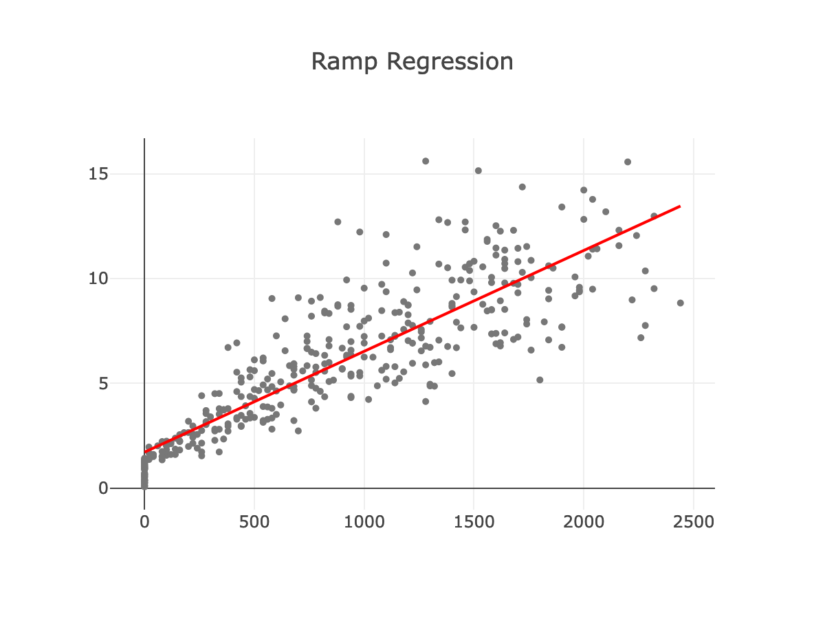
The gray points are the measurements made by the tuner, and the red line is the
line of best fit. Its from this line that the feedforward parameters will be
extracted. In fact, you can see preliminary values for kS and kV already
displayed above. But those estimates are limited by the presence of outliers.
You can see that the red line doesn’t quite fit the trend. Let’s help the
algorithm out by manually filtering out outlier points.
First, click and drag to select a rectangular region of the plot:

Then to remove those points, press the “e” key or the “exclude” button above. The selection box will disappear, and the points will turn a lighter gray. After repeating this process as many times as necessary, you should end up with a plot like this:
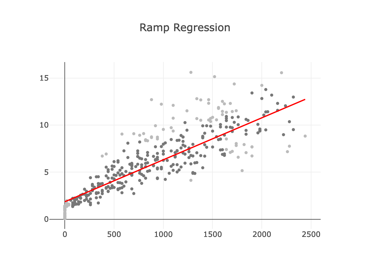
Now you can copy the values above the plot into the kS and kV fields in the
drive class.
If you mess up and accidentally exclude non-outlier points, select them and press “i” or click the include button to bring them back into the calculation.
If you have issues or the data looks weird, click the “Download” button to retrieve your data and include it when asking for help.
LateralRampLogger (mecanum with dead wheels only)
#
Goal: determine lateralInPerTick empirically
If all is configured correctly, the logger OpMode will move the robot to the left,
increasing in speed as it goes (similar to ForwardRampLogger). Stop it at any point,
keeping in mind that longer runs will collect more data.
When you’re done, go to http://192.168.43.1:8080/tuning/lateral-ramp.html and click
the “Latest” button. The slope reported is lateralInPerTick.
A multiplicative factor alone unfortunately doesn’t adequately capture the strafing behavior of most robots. It’s common to see a plot with a plateau in the beginning:
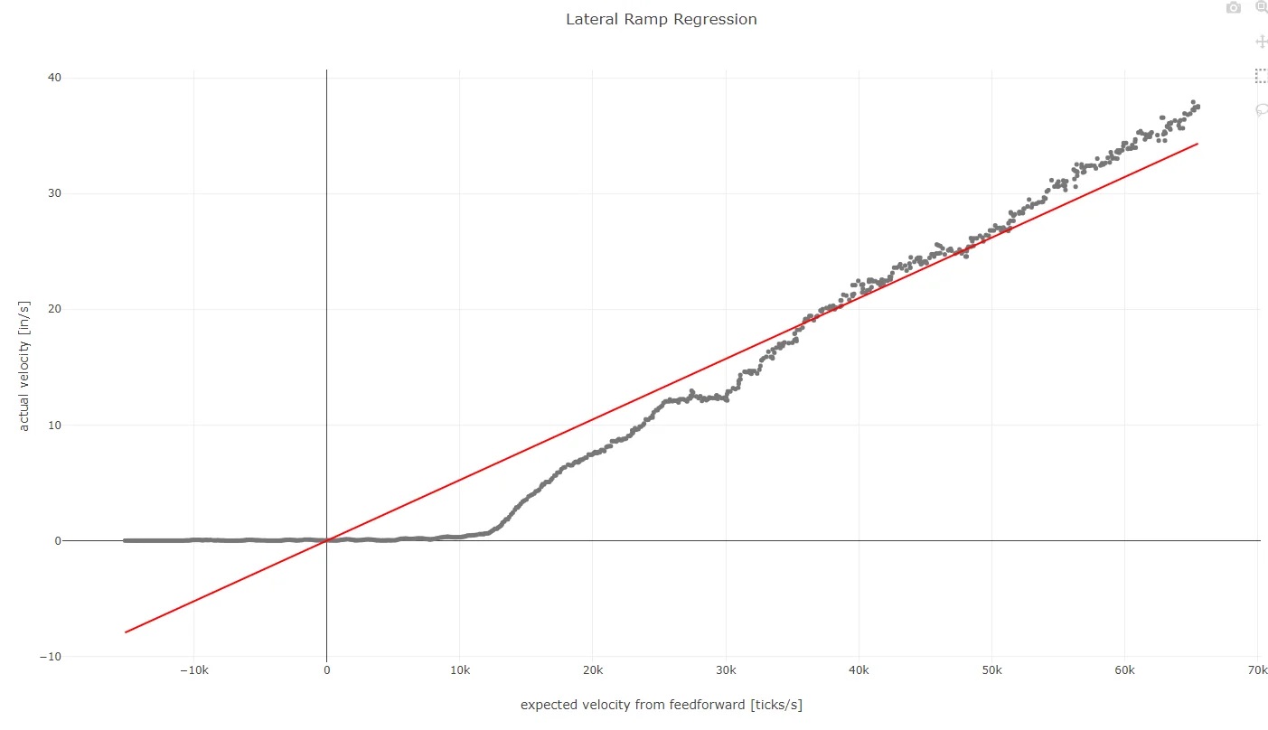
There’s nothing much to be done about the poor fit during tuning. Future versions of Road Runner may change the strafing model to get a better fit (progress will be tracked on this issue).
AngularRampLogger
#
This routine is very similar to the last except that it rotates in place instead
of moving forward. As before, you can change the power ramping parameters inside
the power() method. Run the routine using the same instructions.
Drive Encoders #
Goal: determine trackWidthTicks, kS, and kV empirically
Go to http://192.168.43.1:8080/tuning/drive-encoder-angular-ramp.html and click
the “Latest” button. Use the instructions from the ForwardRampLogger analysis
to get kS, kV from the the “Ramp Regression” plot. Then use the same
outlier-exclusion technique on the “Track Width Regression” and set
trackWidthTicks to the “track width” value when you’re finished.
Dead Wheels #
Goal: determine trackWidthTicks and odometry wheel locations empirically
Go to http://192.168.43.1:8080/tuning/dead-wheel-angular-ramp.html and click
the “Latest” button. Copy the kS and kV values from ForwardRampLogger into
the appropriate boxes and click the “update” button. Use the instructions from the
ForwardRampRegression analysis to fill in trackWidthTicks in your
drive class and the wheel position fields in your dead wheel class. There should
be multiple plots. Scroll down to make sure you don’t miss any.
To get an accuratetrackWidthTicksvalue, you need accurate values forkS,kV.
ManualFeedforwardTuner
#
Goal: Fine-tune kS, kV and add in kA
This routine repeatedly drives forward and back DISTANCE units, giving you an
opportunity to finalize the feedforward parameters.
Open FTC Dashboard by navigating to http://192.168.43.1:8080/dash. Run the op
mode, and graph vref against v0. Set kA to a small value like 0.0000001
and slowly increase it by a factor of ten until it starts effecting the plot.
Try to make the two lines in chart as close together as possible.
At this point, the robot still has no feedback and may drift over many cycles. Pressing Y/Δ (Xbox/PS4) will pause the tuning process and enter driver override, allowing you to reset the position of the bot. Pressing B/O (Xbox/PS4) will return to the tuning process.
ManualFeedbackTuner
#
Goal: Tune the feedback parameters
This routine also goes back and forth DISTANCE units but using combined
feedforward and feedback.
Use this opportunity to tune the feedforward parameters of your trajectory following controller.
MecanumDrive: There are two gains for each travel direction (forward, lateral, heading). The first (“position gain”) is like the proportional term of a position PID, and the second (“velocity gain”) is like the derivative term of a position PID. Here are some tips- Focus on tuning one parameter at a time.
- Start by setting a small value like
1and adjust from there. - Nudge the robot to introduce disturbances and watch them be corrected.
- Skip the velocity gains unless you know what you’re doing.
TankDrive: The two Ramsete gains shouldn’t need much tuning. According to the FRC Docs, “Larger values ofbBarmake convergence more aggressive like a proportional term whereas larger values ofzetaprovide more damping in the response.”
SplineTest
#
This routine follows a basic spline and validates the previous steps.
OTOS-Exclusive Tuners #
Goal: Tune the OTOS device. These steps should be done before tuning the rest of the robot.
OTOSAngularScalarTuner
#
This routine will help you determine the angular scalar for the OTOS device. Press start and rotate the robot 10 times (3600 degrees) in place. Once you are done, copy the angular scalar displayed by telemetry into the angular scalar parameter in OTOSLocalizer
OTOSLinearScalarTuner
#
This routine will help you determine the linear scalar for the OTOS device. Press START and drive the robot forward a known distance. Once you are done, set the linear scalar parameter in OTOSLocalizer “Uncorrected Distance Traveled X” value divided by the actual distance traveled.
OTOSHeadingOffsetTuner
#
This routine will help you determine the heading offset for the OTOS device.
Place the side of the robot against a field wall and press START, then push the robot forward a known distance.
Once you are done, set the h argument to the Pose2D in
the offset variable in OTOSLocalizer
to the displayed “Heading Offset (radians)” value.
OTOSPositionOffsetTuner
#
This routine will help you determine the position offset for the OTOS device.
Place the robot in the corner of two field walls and press START,
then rotate the robot 180 degrees and push it back into the corner.
Then copy the displayed “X Offset” and “Y Offset” values
into the x and y arguments to
the offset variable in OTOSLocalizer